This
project was done during my post graduation diploma course. I was given a task
to develop and complete a security device for a car. I developed a model using
a GSM, GPS and RFID security system.
The project describes how to
implement a car security system using a Global System for Mobile Communication,
Global Positioning System and Radio Frequency Identification modules. Basically
the procedure is to access the car using a key as usual. However, in case of any
theft issue, the owner can send a message from his pre registered phone number to
the GSM module fitted in the car and he will receive the current location of
the device (car). Another message can stop the car engine and the device
demands RFID verification. The car cannot be started until the RFID card is
verified successfully.
Basic modules in the project
are:
- RFID detector and two cards.
- GPS module
- GSM module
- Coordinating Unit
- A PIC Micro controller – PIC16F876A.
A walk through the details :
Now, I will take you through
a deeper explanation of the project, features, its advantages and
disadvantages. As I mentioned earlier, the device can take control over the
engine functions and stop the engine from working. Under normal condition, the
car engine functions as normal as any other engine. Whereas when the device
receives a message from a pre-stored GSM number, it acts as a master and takes
control over the functioning of the engine. The owner can send a message:
location, the GSM modules installed in the car verifies the message and the
phone number and replies with the latest data received from GPS to the owner.
If the data in message is – stop, the device starts monitoring the car engine.
The device requests RFID verification when the car engine is tried to start the
next time. The car does not start until it clears the RFID verification.
Module wise description:
Global Positioning System – the GPS device that I used is a standalone device
that has four pins. The pins are +5V, Din, Dout and GND.
The GPS device provides lots of information. One needs to separate the desired
or required information. Here is a sample of the GPS message from the device that
I used:
$PMTK010,001*2E
$GPGGA,235946.055,8960.0000,N,00654.0000,E,0,0,,137.0,M,13.0,M,,*4C
$GPGSA,A,1,,,,,,,,,,,,,,,*1E
$GPRMC,235946.055,V,8960.0000,N, 16650.0000,E,0.00,0.00,050180,,,N*72
$GPVTG,0.00,T,,M,0.00,N,0.00,K,N*32
$GPGGA,235947.054,8960.0000,N,
16650.0000,E,0,0,,137.0,M,13.0,M,,*4C
$GPGSA,A,1,,,,,,,,,,,,,,,*1E
$GPRMC,235947.054,V,8960.0000,N,
16650.0000,E,0.00,0.00,050180,,,N*72
And it goes on. So, in order to find the location as
per my requirement in this project, all I need is the data in the row that
reads: $GPRMC
So using a simple do-while loop and if-else ladder I
can pull out the required data.
------------------------
I have generated a HEADER FILE (GPS.h file) that you
may use in your program.
-----------------------
Now you can store the received data to a character
array. This array can be later transmitted through the GSM module to a desired
number.
To check the functioning of GPS module, you can
connect your device to the PIC micro controller and transmit the data through
the serial port to the computer. You will have to use the RS232 conversion by
using a MAX232 chip (from MAXIM) and a DB9 port to transmit the data to
computer.
I used a baud rate of 9600. You can see the
transmitted data on the computer screen in a Hyper Terminal.
Global System for Mobile Communication – The module that I used had two features. It supports
both GSM and GPRS. In order to connect the GSM module to a computer you will
have to make use of the serial port. This one does not require a RS232
conversion while directly connecting to the computer. However, while you
connect the GSM to a PIC micro controller, you will require a RS232 conversion.
To transmit and receive GSM data, use the standard AT
commands.

------------------------
I have generated a HEADER FILE (GSM.h file) that you
may use in your program.
-----------------------
The received data through the GSM can be stored in a
location if necessary. Read the message in the GSM and using a switch control,
activate the RFID task of the GPS task.
If the message content is location, reply to the number with current GPS data and if the
message content is stop, activate the
RFID verification. This action will monitor the functioning of the car engine.
The next time when the car engine is started, the device will demand RFID
verification.
As I mentioned before, the car engine cannot be
started unless the RFID is verified successfully.
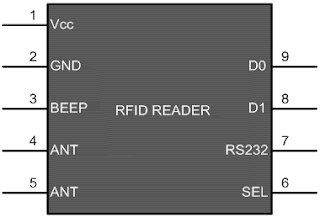
Radio Frequency Identification module – The RFID module that I used has a DB9 port. You can
connect this device to your computer directly through a serial port and can
read the RFID card number that you are using, in the Hyper Terminal.
The RFID card reader needs to be connected to the PIC
micro controller through a MAX232 chip (RS232 conversion is required). The card
number is pre-stored in a character array and is compared during RFID
verification process.
------------------------
I have generated a HEADER FILE (RFID.h file) that you
may use in your program.
-----------------------
A special circuit - The PIC micro controller PIC 16 F 876 A that I used
had a software UART (Port C) in terminal as well as a hardware UART terminal. I
preferred to use hard ware UART transmission.
However, for the project I required three UARTs one
each for GSM, RFID and one to the computer for checking purpose (This part can
be used to connect to a display unit to display the data on a LCD screen in the
device). The GPS module is directly connected to the PIC.
Hence, I developed a small circuit board with four
relay switches and four DB9 ports. One of the port is connected the PIC micro
controller and the rest to the other devices. The model of the circuit and
circuit diagram is given below.


